User Tools
Sidebar
Table of Contents
FAQ all products
Firmware Support Rules
At Kerlink, we are committed to supporting all our customers, regardless of the software version they are currently using.
To ensure you benefit from the latest improvements and corrections, new features and defect fixes are provided exclusively on the most recent official release.
For certain investigations, Kerlink may request that your equipment be updated to the latest release in order to guarantee efficient and accurate support.
We strongly recommend keeping your equipment up to date with the latest official version to enjoy optimal performance, security, and access to the newest functionalities.
To stay informed about new releases, you can easily subscribe here: Kerlink Wiki News.
For more details on the software versions currently supported from a security perspective, please visit: Kerlink Security Support.
How to know the password to connect in SSH according to the product and the version?
Start an SSH client (typically Putty on Windows) using the gateway’s name or IP address (the port is the standard 22).
After getting a prompt: enter login/password (e.g. “root / password”).
Wirnet i-series gateways
Default password is built using the last 6 digits of the serial number, CPU module S/N for Wirnet iBTS and board ID for other Wirnet Gateways: pdmk-$serialno (case sensitive).
For example:
If a Wirnet iBTS has 729ATf061ECD as CPU module ID, the password will be: pdmk-061ECD
If a Wirnet iFemtoCell has 704BEc1234AB as board ID, the password will be: pdmk-1234AB
This 6 digits numbers can also be retrieved in the hostname. It is displayed in the shell prompt:
Keros (Kerlink OS Distribution) 4.3.3 klk-lpbs-0507DD /dev/console
klk-lpbs-0507DD login: root
Password: pdmk-0507DD
Wirnet Station gateways
| Firmware version | Login | Default password |
|---|---|---|
| 2.x | root | root |
| 3.1 | root | pdmk-0<serialno_last_7_characters_lowercase> |
| >=3.3 | root | pdmk-0<serialno_last_7_characters_uppercase> |
Examples:
- For Firmware 2.2.1: the default password is root.
- For Firmware 3.1: if the Wirnet Station serial number is 0xB0E032D, then the root password will be pdmk-0b0e032d
- For Firmware 3.3: if the Wirnet Station serial number is 0xB0E032D, then the root password will be pdmk-0B0E032D
How to take charge of my product?
For each Kerlink gateways, you can find a Setup page which gathers all the information you need to get started with your product. To access directly to these pages, go to KERLINK WIKI homepage https://wikikerlink.fr/. Click on the desired product to arrive on the product quick start page.
Where to find LoRaWAN gateways installation recommendations?
An application note providing guidelines to anticipate the gateways installation is available on KERLINK WIKI. Go to https://wikikerlink.fr/wirnet-productline/doku.php?id=wiki:resources:resources#application_notes, section Application notes. This application note could be considered as a check list, before installing the gateways, to make sure all critical parameters are identified and will be properly addressed during the installation.
Where to find information about LoRaWAN gateways lightning protection?
An application note providing guidelines to understand the lightning phenomenon, its consequences, and solutions to protect the electronic devices in general, and LoRaWAN gateways more specifically is available on KERLINK WIKI. Go to https://wikikerlink.fr/wirnet-productline/doku.php?id=wiki:resources:resources#application_notes, section Application notes.
How to improve radio coexistence performance of LoRaWAN gateways?
An application note providing information about radio coexistence performance of LoRaWAN gateways is available on KERLINK WIKI. Go to https://wikikerlink.fr/wirnet-productline/doku.php?id=wiki:resources:resources#application_notes, section Application notes.
This application note details the phenomenon which could cause desensitization of the LoRaWAN gateways because of the colocalized transmitters i.e.:
- Out of band blocking
- In band blocking
- Third order intermodulation
- Generation of out of band noise (spurious)
The application note also provides some recommendations to avoid desensitization by using:
- RF filters by design - embedded in the gateway
- External cavity filters, for specific harsh environments
- Installation recommendations to minimize interferences.
How to optimize LoRaWAN gateways coverage?
An application note providing some basics to understand how to determine the radio coverage and moreover how to optimize it thanks to an appropriate installation is available on KERLINK WIKI. Go to https://wikikerlink.fr/wirnet-productline/doku.php?id=wiki:resources:resources#application_notes, section Application notes.
Where to find documentations about Accessories?
The accessories recommended by KERLINK for a product are listed in its leaflet. The leaflets are accessible from the quickstart page of each product, section Documentation. To access directly to these pages, go to KERLINK WIKI homepage https://wikikerlink.fr/. Click on the desired product to arrive on the product quickstart page.
The datasheets of the accessories are then available on https://wikikerlink.fr/wirnet-productline/doku.php?id=wiki:resources:resources#application_notes, section Accessories documentations.
Why did my magic link not work?
My magic link may not work for the following reasons:
- My gateway is new and has not been added to the magic link by the KERLINK support team
- My gateway does not have internet access
- Internet speed is too low
If necessary, you can contact the support team via OTRS or by email to support@kerlink.fr by sending the following information:
Customer:
WMC Instance:
Fleet:
Model: ex: Wirnet iStation 915
Product ID:
Region: ex: EU868 US915 RU864
EUI:
How to do a factory reset on a KERLINK gateway? What to do when losing all my passwords?
Wirnet i-series gateways
Factory reset can be done:
- By the web interface gateway administration menu (password of the web interface required)
- By SSH access (root password required). The stock firmware is backuped at production time (or when updated with a KerOS liveburner.ipk file). A “stock restore” will factory reset the gateway. All data will be lost. To trigger a stock restore execute the following commands:
kerosd -s
reboot
- By a manual stock restore (no password required, available since firmware 4.1).
To manually trigger a stock restore on a Wirnet gateway (excepting iFemtocell), please follow this procedure:
- Unpower the gateway by pushing ON/OFF button more than 5 seconds.
- Make sure Power led is off and release button.
- Push On/OFF button to power-up the gateway and maintain until power and status leds blink alternatively. At this step, the gateway is ready to execute a stock restore operation. It will wait for a confirmation during 10 seconds.
- Release button and push it again to confirm the operation (leds will then stop blinking alternatively).
- Wait for the end of this operation (Leds behaviour described here). It takes approximately 2 minutes.
This procedure works for all Wirnet gateways excepting Wirnet iFemtocell which doesn't have an ON/OFF button.
For iFemtoCell:
- Push WPS button and maintain it.
- Push Reset button one second. At this step, the gateway is ready to execute a stock restore operation. It will wait for a confirmation during 10 seconds.
- Release WPS button and push it again to confirm the operation (leds will then stop blinking alternatively).
- Wait for the end of this operation (Leds behavior described here). It takes approximately 2 minutes.
Wirnet Station gateways
- To factory reset the gateway, you can burn the factory firmware images using a USB flash drive with a firmware available in the wiki Resources page.
- You can also trigger the recovery mode:
By default, the userfs partition /mnt/fsuser-1 is not impacted by the recovery process. The eMMC partition /mnt/mmcblk0p1/ is not impacted by the recovery process.
- You have access to the system (ssh or console): In order to force the gateway to re-install itself, enter the following commands:
fw_setenv bootfail 100
reboot
- You have a debug probe access: Enter in the Uboot shell by pressing the key “k” of the PC keyboard at early boot time, then type
watchdog disableto stop the watchdog (else the reboot happens every 30s).
Product: WirmaV2 lora V
  WARNING: Machine type unknown, set default wirmaV2 Module
  Autoboot in 1 seconds, enter Password:
  KLK-Uboot> kkkkkkkkkkkkkkkkkkkkkkkk
  Unknown command 'kkkkkkkkkkkkkkkkkkkkkkkk' - try 'help'
  KLK-Uboot> watchdog disable
  Watchdog disabled
-Set the recovery mode
setenv bootfail 100
saveenv
reset
- You don't have access to the system: You can manually force the gateway to enter into the recovery mode: you have to reset the gateway 22 times.
- Power on the system.
- Press and release the reset button.
- Wait between 4 and 10 seconds.
- Repeat point 2. and 3. 22 times!
How to correctly configure a SIM Card APN?
Wirnet i-series gateways
Mandatory information to configure your gateway is:
- The operator MCC (Mobile Country Code) value
- The operator MNC (Mobile Network Code) value
- The APN (Access point name) of the SIM card
The Cellular configuration can be done:
- Using the web interface: Go in the Network configuration panel and add your operator in the list.
A reboot of the gateway is required after cellular configuration to take into account modifications done via Web interface.
- Using configuration file: The oFono daemon is used to configure the modem. oFono configuration is done via the editable configuration file
/etc/network/ofono/provisioning.
It is used to define APN, PIN code and cellular context. Example of configuration is available in the default provisioning file.
To update oFono with the last configuration, each time the provisioning file, or the SIM card is changed, a service reset has to be performed: /etc/init.d/ofono reset.
Roaming use case:
- If a roaming SIM card is inserted in the gateway, the MCC/MNC codes to configure should be those ones of the SIM and not those of the local operator.
- The APN to configure is the one of the SIM providers also, not the one of the local operator.
Wirnet Station gateways
To configure the GPRS auto connection and the link monitoring at startup:
- Set your APN in
/etc/sysconfig/network:
# Selector operator APN
GPRSAPN=m2minternet
# Enter pin code if activated
GPRSPIN=
# Update /etc/resolv.conf to get dns facilities
GPRSDNS=yes
# PAP authentication
GPRSUSER=kerlink
GPRSPASSWORD=password
- Reboot the system to apply the modification.
How to configure WiFi on a iFemtoCell?
The WiFi configuration can be done:
- Using the web interface:
Go in the Network configuration panel. Choose your Wi-Fi access point in the list. Click on the access point name.
- For passphrase-protected WiFi, fill the passphrase in the newly opened window and click “Connect”.
- For WPS-enabled Access Point, or if your WiFi AP is opened, just click “Connect”. The Wi-Fi network will appear connected in front of the network name.
- Using configuration files:
ConnMan’s WiFi (wlan) Ethernet configuration is done via the editable configuration file /etc/network/connman/wlan.config.
To manually configure a WiFi network, the fields Name and Passphrase must be changed.
Connman supports multiple WiFi 'services' descriptions. Just add a new 'service' with another name than “service_WLAN”.
It also supports various type of configuration (static, tls, peap, …).
- Using the WPS button:
The WPS button of the Wirnet iFemtoCell can be used simply to connect the gateway to a WiFi network.
The WPS button is signalled by a WiFi symbol on the gateway.
- Press the WPS button of your WiFi access point.
- Press the WPS button of the Wirnet iFemtoCell.
- The association is done between the gateway and the WiFi access point.
How to configure a static IP on a KERLINK gateway?
Wirnet Station gateways
Edit the network configuration file /etc/sysconfig/network.
Disable DHCP requests: set the field to no instead of yes.
# claims dhcp request on eth0
ETHDHCP=no
Modify the Ethernet configuration with parameters you want.
# if static addr is selected on eth0
ETHIPADDR=192.168.4.155
ETHNETMASK=255.255.255.0
ETHBROADCAST=192.168.4.255
ETHGATEWAY=192.168.4.1

# manual DNS server
DNSSERVER1=9.9.9.9
DNSSERVER2=208.67.222.222
Then restart the network script /etc/init.d/network restart, or reboot the Wirnet Station.
Wirnet i-series gateways
ConnMan’s LAN Ethernet configuration is done via an editable configuration file /etc/network/connman/lan.config. This file is not created by default on the gateway. A configuration file /etc/network/connman/lan.config.example is provided.
Once file /etc/network/connman/lan.config is created, relaunch ConnMan to apply the configuration /etc/init.d/connman restart.
By default DHCP is used, there is no default IP address. To use static IP addressing, the field IPv4 can be changed, for example, from
IPv4 = dhcp
to
IPv4 = 192.168.1.5/24/192.168.1.1
Where 192.168.1.5 will be the new IP address of the Wirnet gateway, 24 will be the subnet length (in bits), and 192.168.1.1 will be the default gateway.
If DNS resolution is needed, the Nameservers field can be added. Multiple addresses can be used. For example:
Nameservers = 192.0.2.1,192.0.2.2
ConnMan automatically detects the changes and applies them when the configuration file is closed.
How to configure the KERLINK CPF for i-series gateways to connect to an LNS?
Since firmware 4.3.x, CPF is installed in Keros firmware. The configuration is achieved in 2 steps:
- lorad configuration
- lorafwd configuration
lorad configuration
The goal of the lorad configuration is to define the frequency plan that will be used to receive packets from the end-devices, to enable the LBT feature and to configure the class B beacons.
- A few frequency plan templates are pre-installed on the gateway (under
/etc/lorad/PLATFORMwhere PLATFORM equal to ibts, wifc, wiis or fevo): it is strongly recommended to copy the expected frequency plan templates in/etc/lorad/lorad.jsonfile. The goal is to keep templates unmodified. - Edit
/etc/default/loradand make sure that theCONFIGURATION_FILEfield links to the template you previously copied. - Edit
/etc/default/loradand make sure thatDISABLE_LORAD=“no”is present in this file. If lorad is disabled consult the following page to activate the CPF: Keros application configuration. - Edit the template you copied to adapt it to your needs. Since the hardware between gateways is different, the configuration on each gateway differs (although it is quite similar).
lorafwd configuration
The goal of the lorafwd configuration is mainly to define to which LNS LoRa packets will be forwarded to.
- Edit
/etc/default/lorafwdand make sure thatDISABLE_LORAFWD=“no”is present in this file. If lorafwd is disabled consult the following page to activate the CPF: Keros application configuration. - Edit
/etc/lorafwd.toml. This configuration file is formatted using the TOML v0.5.0 language:- Most keys are pre-configured with correct values.
- The description of each key is directly written in the configuration file. If this configuration file has been modified, use
/etc/lorafwd.toml.exampleas a model - Hereunder are the keys that must be changed to chose your LNS:
gwmp.node = “localhost”: The address of the LNS.gwmp.service.uplink = 20000: The uplink port of the LNS.gwmp.service.downlink = 20000: The downlink port of the LNS.
Note that the configuration of the downlink port, uplink port and LNS address can be done directly in the CPF activation comman: Keros application configuration.
How to configure a TTN LNS with the Kerlink Firmware ?
To configure your Kerlink gateway to send messages to the TTN network you can consult the TTN website: https://www.thethingsnetwork.org/docs/gateways/kerlink/
For firmware version 4.3.3 and above, activate the CPF on european TTN server with the command:
klk_apps_config --activate-cpf --lns-server router.eu.thethings.network --lns-dport 1700 --lns-uport 1700Keros application configuration examples
How to configure a push on WMC?
Define your push configuration
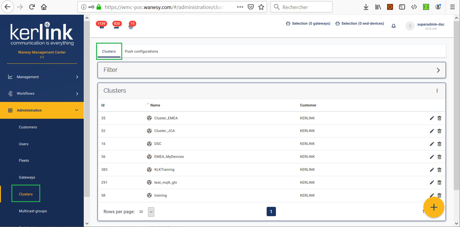
Select the “Push configurations” after selecting Clusters from the Administration menu:
Click the following link to see how to proceed: https://wmc-poc.wanesy.com/docs/administration/create-push-configuration.html
(if needed, replace the URL domain wmc-poc.wanesy.com by your own WMC)
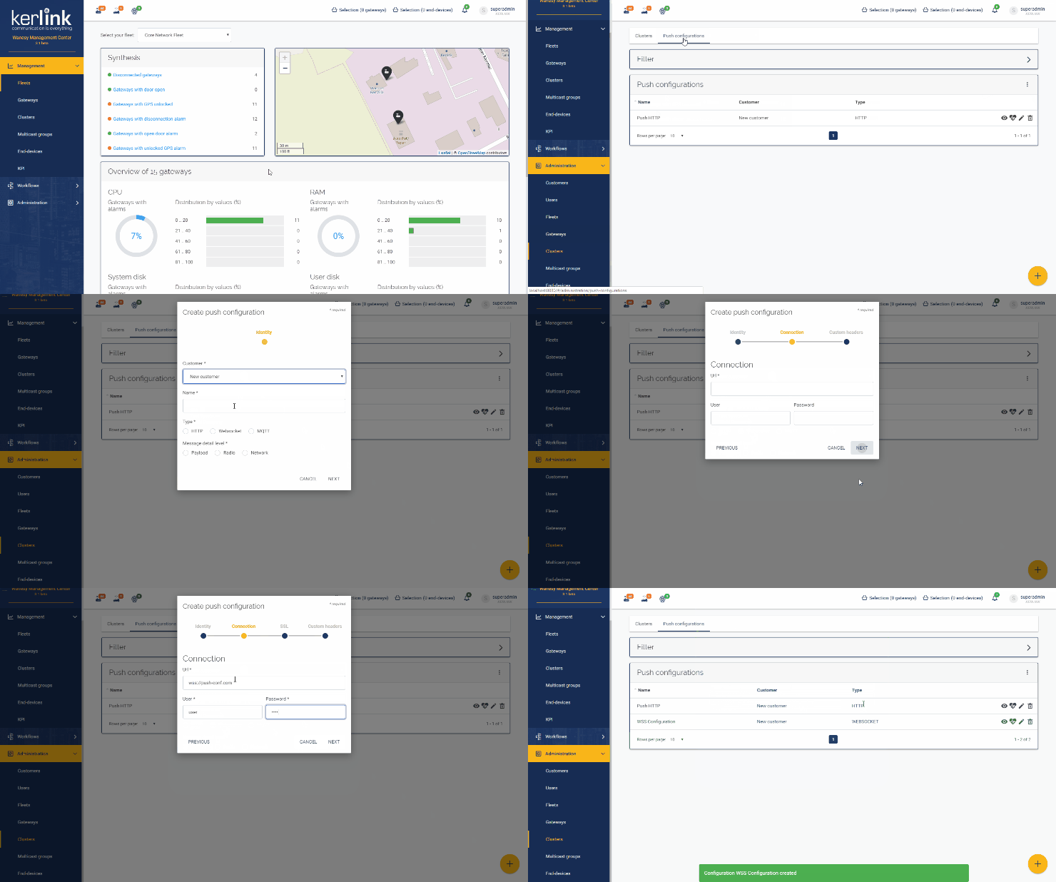
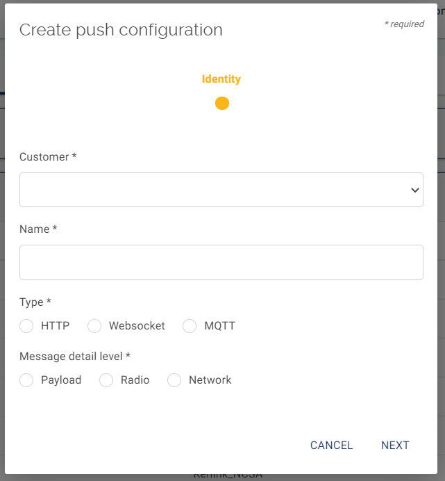
Define Identity parameters for your push configuration
To create a push configuration, you need to define the following information:
- Customer: select your name
- Name of this push configuration
- Type: type of protocol to use: HTTP, Websocket or MQTT
- Message detail level: this field sets the granularity of the returned information.
For message detail level, 3 levels are available (from the less detailed to the more detailed):
- Payload : Returns only the userdata tag without motetx information filled by the packet forwarder.
- Radio : Adds the RF metadata information: deviceEui, time, tmst, freq, stat, modu, datr, codr.
- Network : Adds the gateway Rx information: gwEui, rfRegion, rssi, lsnr, channel, radioId, antenna.
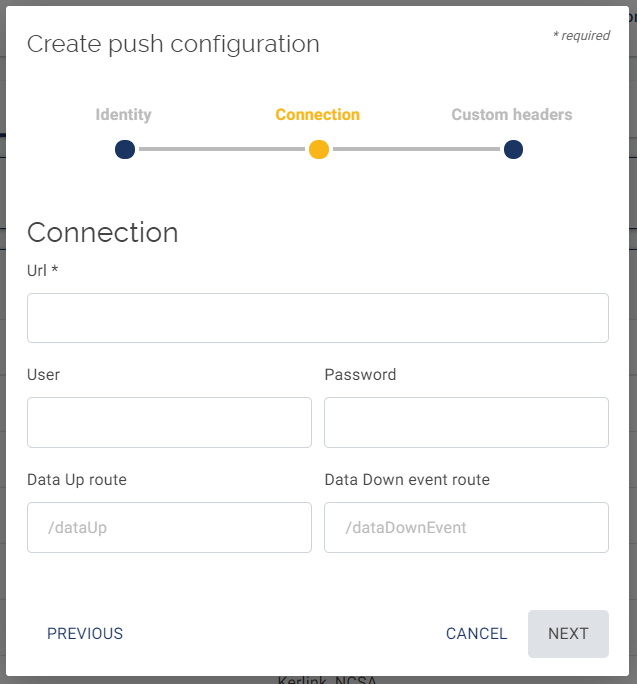
Define Connections parameters in your push configuration
To define the connection parameters, you need to specify :
- Url: your Application Server (AS) url: where to send push data.
- User: User account for your AS
- Password : password for your AS
- Data Up route: specific route where to send push data for uplink messages
- Data Down event route: specific route where to send push data for downlink messages
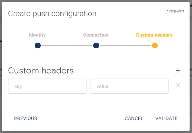
Define Custom headers in your push configuration (optional)
Specify your push configuration for your cluster
Select the “Clusters” option after selecting Clusters from the Administration menu:
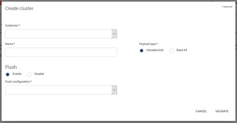
The “Push configuration” can be added during the cluster creation or on an already existing cluster with the “edit” option (pen on the right side).
Fill the following information :
- Customer (mandatory): select your name
- Name (mandatory): enter a name for the new cluster
- Payload type (mandatory): select the payload format (Hexadecimal or Base64).
- Enable/Disable (optional): select Enable to enable the push feature. Default is Enable.
- Push configuration (mandatory): select the push configuration you have previously just defined.
How to configure the Tx power of a gateway?
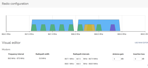
In order to adjust the Tx power of a gateway, the antenna gain, the insertion losses and regulations must be taken into account. In the CPF lorad frequency plan configuration file, you can indicate the gateway antenna gain and the insertion loss value.
- Antenna_gain: Is used to define the gain of the antenna. This field must be correctly filled, otherwise, the gateway will use more power to emit packets than what was initially planned by the LNS.
- Insertion_loss: Is used to define the attenuation due to the cable between the gateway and the antenna (example: use of a cavity filter).
In WMC web interface, these fields can be checked and modified in the radio configuration page of each gateway.
How to configure and use CFlist?
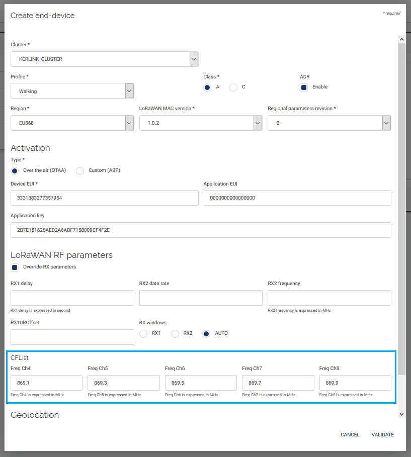
CFlist stands for Channel Frequency list.
CFList is a list of five channel frequencies for the channels three to seven whereby each frequency is encoded as a 24 bits unsigned integer (three octets).
LoRaWAN implements this CFList of 16 bytes in the JoinAccept message.
The CFList is optional and its presence can be detected by the length of the join-accept message.
If present, the CFList SHALL replace all the previous channels stored in the end-device apart from the three default channels.
The newly defined channels are immediately enabled and usable by the end-device for communication.
The format of the CFList is region dependent.
Refer to the LoRaWan Regional Parameters v1.0 specification to get details about these 16 bytes.
How to configure network delays?
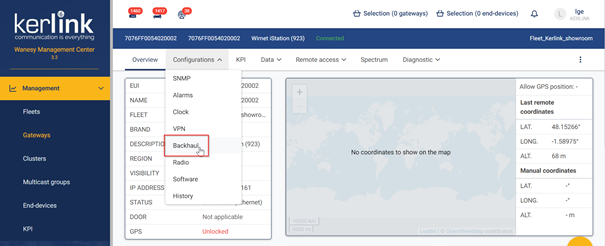
From the Backhaul configuration menu of each gateway, the network delay uplink and downlink can be configured. The default configuration is 350ms.
On the WMC web interface, go to Managements → gateways. Click on the gateway_EUI and go to Configurations → Backhaul
This value is an indication of the network delays that the gateway has towards and from the LNS server.
The latency of the gateway can be evaluated from the ping (delay up + delay down) KPI.
On a fast network, to target the RX1 window with maximum anticipation, the following configuration must be set:
| Network max. delay up | Network max. delay down |
|---|---|
| 0 | 400 |
On a slow network, to target the RX2 window with maximum anticipation, the following configuration must be set:
| Network max. delay up | Network max. delay down |
|---|---|
| 0 | 1400 |
See Network delays page for more details
What is the difference between a private and a public gateway on WMC?
A public gateway is a gateway that can be used by all the devices declared in the WMC instance. A private gateway is a gateway that is only used by the end-devices declared for the customer it belongs.
How to get logs? How to increase level of logs?
Wirnet i-series gateways
Gathering logs from shell since release 4.2
- Execute the command
get_logs. The execution of the script takes less than 1 minute.
- It will generate an archive in the same directory you executed the script (example:
Logs_2E0605F5_7b26_20200124-095206.tar.gz).
- Retrieve this archive (use whatever method you prefer: FileZilla, scp, …).
Gathering logs from shell on older releases
- Upload the script get_log.sh (use whatever method you prefer: FileZilla, scp, copy/paste, …) in a folder of your gateway and go to this folder.
- Convert the file to Unix text file format using
dos2unix get_logs.sh. - Add execution rights to the script using
chmod 755 get_logs.sh. - Execute the script using
./get_logs.sh. The execution of the script takes less than 1 minute. - It will generate an archive in the same directory you executed the script. (example:
Logs_2E0605F5_7b26_20200124-095206.tar.gz) - Retrieve this archive (use whatever method you prefer: FileZilla, scp, …).
Gathering logs from USB (no commands required)
- Download the script usb.autorun and copy it on a USB flash drive.
- Create a
usbkey.txtfile on the USB flash drive as described here. - Plug the USB flash drive into the USB port of the gateway.
- Wait for the yellow debug led fast blinking. The execution of the script takes about 1-2 minutes.
- Unplug the USB flash drive.
- An archive with all the required logs has been created on the USB flash drive.
Wirnet Station gateways
Gathering logs from shell
Execute the command below to create an archive which contains all the logs. (Copy/paste all the lines at once, this is only one command)
uname -a > /tmp/status; \
date >> /tmp/status; \
uptime >> /tmp/status; \
ps >> /tmp/status; \
get_version >> /tmp/status;\
ls -al /etc/rc.d/rc3.d/ > /tmp/boot_time_scripts_list; \
head -n 10 /dev/nmea > /tmp/nmea;\
tar -czvf logs_klk_`hostname`_`date +%s`.tar.gz \
    /mnt/fsuser-1/trace_agent/    \
    /var/log/*                    \
    /knet/knetd.xml               \
    /etc/                         \
    /tmp/status                   \
    /mnt/mmcblk0p1/*.log*         \
    /mnt/fsuser-1/openvpn/traces/ \
    /mnt/fsuser-1/lorad/etc/      \
    /mnt/fsuser-1/lorafwd/etc/    \
    /mnt/fsuser-1/bscc/traces/    \
    /mnt/fsuser-1/snmp/traces/    \
    /mnt/fsuser-1/lora/var/log/   \
    /mnt/fsuser-1/spf/var/log/    \
    /mnt/fsuser-1/spf/etc/global_config.json \
    /tmp/nmea \
    /tmp/boot_time_scripts_list''
Then use your favourite tool (WinSCP, a USB stick, scp,…) to download the file logs_klk_“YOUR_SERIAL_NUMBER”_“EPOCH_TIMESTAMP”.tar.gz.
Gathering logs from USB (no commands required)
Download the script autorun_klk.sh and copy it on a USB stick.
Plug the USB key on the Wirnet station.
Wait for the mod2 led fast blinking. The execution of the script takes about 1-2 minutes.
Unplug the USB key.
An archive with all the required logs has been created on the USB stick.
CPF logs management (increase verbosity) on all Kerlink gateways
Both daemons generate logs in the /var/log/lora.log* files.
The verbosity of the daemons can be increased using the “EXTRA_ARGS” field under /etc/default/lorad and /etc/default/lorafwd.
NOTICE = -v: Displays start and stop traces
INFO = -vv: Displays the configuration, uplinks, downlinks…
DEBUG = -vvv: Displays the hexdump of the packets
How to check what is installed on a gateway?
Wirnet i-series gateways
- Since FW v4.x, through Web interface, see the Firmware installed.
- Launch the command
opkg list-installed. - In FW v4.3.3, WMC and CPF packages are included, so you can check the folder architecture:
    /etc/default/lorad
    /etc/default/lorafwd
    /etc/default/bscc
    /etc/default/lora-snmp
    /etc/openvpn/
- Command
monit statuscan be executed to check which processes are running on the gateway.
Wirnet Station gateways
Launch the command get_version -u -v.
Wanesy SPN
The Wanesy SPN version is available on the web user interface. Click on the (i) button in the upper right corner of the screen.
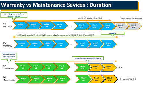
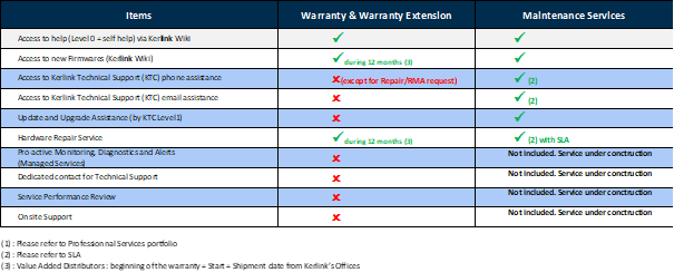
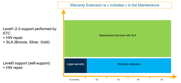
Warranty vs Maintenance Services: Duration and scope of work
What to check if the messages of an end-device are not received on WMC?
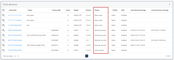
Firstly, check the status of your End-Devices in WMC web interface Menu Management/End-devices
- Potential issues during the JOIN:
- JOIN APPEUI ERR : JOIN REQUEST with invalid AppEui was received and refused ⇒ AppEui doesn't match with the provisioned one
- JOIN DEVADDR ERR: ABP configuration issue with the set DevAddr ⇒ DevAddr may be already in use
- JOIN DEVNONCE ERR : JOIN REQUEST with already used DevNonce was received and refused ⇒ DevNonce has already been used by the end-device
- JOIN MIC ERR : JOIN REQUEST with invalid MIC was received and refused ⇒ Probably due to corruption or invalid AppKey
- End-device with « Never seen » Status failed their “Join”:
- Check if the gateway status is “Connected”
- Check if the frequencies used by the gateway covering this area are the ones used by the end-device
- Check if the end-device is under the gateway radio coverage
- Check in the CPF logs of the gateway near the end-device that it receives messages
- Check if the end-device is correctly declared on the WMC (correct activation parameters, correct region…)
In case of OTAA, check the DevEUI / AppKey / AppEUI of the end-device declared on the WMC.
In case of ABP, check DevEUI / Application session key / DevAddr / Network session key of the end-device declared on the WMC.
What to check if there are issues with downlink messages on WMC?
If you are receiving uplink messages but no downlinks are sent to your end-device:
- Check if there are some error messages in the CPF logs of the gateways covering the end-device.
If you see errors in the CPF logs, it can be due to network delay issue: in this case, check your network latency. In your WMC gateway dashboard, go in KPI menu and choose the ping KPI. If the ping value is not good (>800ms RTT) , you need to go in the “Configuration/Backhaul” menu to change the network delays values. On a slow network, the following configuration must be set:
| network max. delay up | network max. delay down |
|---|---|
| 0 | 1400 |
- Downlink issues can also be linked to duty cycle limitation on the gateway.
Go in the network alarm panel to check if you have duty cycle issue. Depending on the local regulation, the gateway transmission duration can be limited. In this case the gateway stops emitting during the time requested to respect the regulation.
What means DEVNONCE ERR status for an end-device in WMC ?
Type : JOIN DEVNONCE ERR
Description : JOIN REQUEST with already used DevNonce was received and refused.
Potential root cause: DevNonce has already been used by the end-device.
What to check in case of network disconnections?
Most of the time, disconnections are due to the quality of the backhaul (QoS) especially when using a cellular backhaul (with a high network latency).
Possible root causes :
- Hardware issue (ethernet cable problem,SIM card present, etc…)
- Backhaul QoS is bad (high network latency)
- Network monitoring issue
- OpenVPN issues
- SW issues (bugs)
- Power loss issues
Check for a hardware issue
Check the ethernet cable connection, check if SIM card is correctly inserted, etc…
Check the backhaul QoS
Check first if disconnections are due to the quality of the backhaul.
Select the KPI « ping » in the gateway KPI menu.
Look at the average ping and max ping values : if the value is greater than 1s that can explain the disconnections. We can do anything except changing APN to have better results.
Check the network monitoring feature
You can check if Network monitoring is enabled. If disabled, enable it ! See the wiki to know how to proceed. Network monitoring can help to solve some disconnections issues.
Check the network monitoring configuration parameters in /etc/network/networkmonitoring.conf file. Sometimes ICMP protocol is filtered by the network. So in this case, it is recommended not to use the “ping” method but instead choose the “tcp” method (port 80 is never filtered).
Check the connectivity with the OpenVPN server
Perform some ping 10.8.0.1 from the gateway and check for network latencies or issues.
If ping says « unreachable », do an ifconfig command. If the vpn interface is not up and has no ip, check your OpenVPN certificate validity.
Check for the OpenVPN certificate validity
if your gateway is a Wirnet Station, perform the command:
openssl pkcs12 -passin pass:"" -in /etc/openvpn /client-openvpn.p12 -nokeys | openssl x509 -noout -enddate''If your gateway is a i-series gateway (Istation, iFemto, iBTS), ask to the Support team the validity date of the certificate (please, give the serial number of your gateway).
Check for OpenVPN certificate install issue
Try to connect remotely to the gateway. If the connection is unstable (connections and disconnections occur), check that no other gateway has the same VPN IP address (because the same OpenVPN certificate has been installed on several gateways):
Launch the command { echo status; sleep 1; } | telnet localhost 7505 2>/dev/null | grep -i <GW_VPN_IP>.
If the serial change that means that several gateways have the same VPN IP address.
To solve this issue, identify the « bad » gateway and uninstall the openVPN secret bad package and install the good one in one shot (build a specific single OpenVPN package that contains the remove ipk of the bad secret package and the install of the new OpenVPN secret package: Package removal).
Check for firewall issues
Try to connect remotely to the gateway. If you success to connect when the status of the gateway is « disconnected », check the SNMP traffic (select Diagnostic > SNMP).
If you see some « unreachable » errors, check your firewall rules iptables - -list-rules.
If the list is corrupted due to a bug, reboot the gateway.
Check for Power loss issues
Check for power loss alarms. Check in the BSCC logs if you see some power loss messages. Solve the power issue.
What to do in case of FPGA version error in the logs of packet forwarder?
- It is advised to update firmware with the last firmware version and FPGA should be then updated also.
- If you cannot update the firmware, find the corresponding FPGA to your firmware version and update it.
How to install/uninstall SPN firmware?
By default, Wanesy SPN firmware is not installed on Kerlink gateways. Therefore, to install the Wanesy SPN the following steps are required:
- Check the firmware version of the gateway.
- If the firmware is not the expected one, upgrade it.
- Upgrade SPN firmware via Web Interface, SSH or by USB.
Software update over Web interface “recommended”.
- Download the firmware from Resources page. The firmware can be download in the download section of the firmware delivery note. The file is named
liveburner_X.X.X-spn_klkgw-signed.ipk. - Connect to your gateway web interface.
- Go in the “Administration” and “Update” Menu.
- Drag & drop your SPN ipk file and click on “UPDATE GATEWAY”.
- A reboot is required to finalize the update, click on “REBOOT GATEWAY”.
What to check in case of SPN issues?
Firstly, check the logs. Two types of logs are available on the gateway:
- Public log: these logs can be accessed and read by the user. Public logs help the user to install and manage the gateway
- Internal log: these logs can be retrieved by the user. Internal logs are for internal Kerlink debug purposes only. Once retrieved, the logs can be sent to Kerlink for analysis.
Logs can be retrieved thanks to:
- The web user interface log menu
- The local FTP server service
- The USB key service
- Command get_logs on SSH session
Check the operation of the following services:
- Check if the gateway synchronizes its time with NTP server
- Check if the gateway DNS service work well
- Check if you have fix IP address or DHCP
- Check date and time
- Use get_logs command to download all gaetway logs (SSH session)
How to send a downlink command?
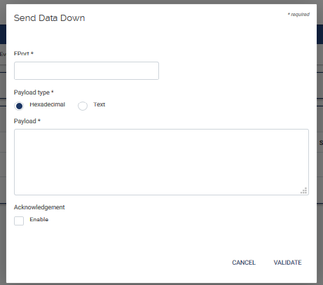
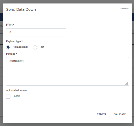
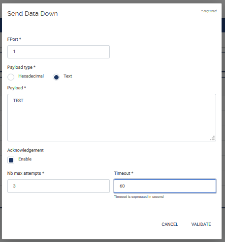
From the WMC dashboard :
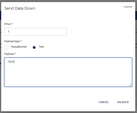
- select « Management » > « End-devices » > « Data Down ».
- Select the « + » icon on the bottom of the page.
- Enter a FPort value (0 for a MAC command, any other value for a command that is not a MAC command, for instance : »1»).
- Select the type of your payload : « Hexadecimal » or « Text ».
- Fill in the payload with your application data.
- Check or not the box « Acknowledgement Enable» if you want to handle ACK for your end-device.
How to send a MAC command?
A MAC command is a downlink command (Server > End-device).
So first read the next section to know how to send a downlink command.
To send a specific MAC command as a downlink message, you need the LoRaWan Regional Parameters documentation from the Lora Alliance:
https://lora-alliance.org/sites/default/files/2018-04/lorawantm_regional_parameters_v1.1rb_-_final.pdf.
The MAC commands are dependant of your region.
Here is an example to set SF12 for end-devices using the ADR feature for EU-868 frequency band:
MAC command: LinkADRReq
If you want to set SF12, use the following parameters:
Type: LinkADRReq
DataRate: 0
TxPower: 1
chmAsk: 7
chMaskCtrl: 0
NbTrans:1
Encode the payload like this:
03 01 07 00 01

03: LinkADRReq
01: DataRate:0 (SF12) & TxPower:1 (MaxEIRP-2dB=27dBm-2dB)
07 00: = 0x0007 means using channels 1,2,3
01: Redundancy bits that mean NbTrans=1 and chMaskCtrl=0 (using channels 1 to 16).
Note that this format uses the little endian format, i.e you have to reverse bytes for fields that uses more than 1 byte. For instance, to activate 8 channels, you should encode the chMask as FF 00 (=0x00FF).
What to check before asking for an after-sales return?
- Check if the gateway starts and boots (login prompt by debug probe or SSH).
- If the gateway doesn’t start at all (no LED), try with another Power Supply (PoE, cables, Power adaptor…).
- If the issue is a SIM issue, check that the SIM is well functional in another equipment and try the gateway with another functional SIM.
- If this is a LoRa issue, meaning that no packets are received by your LNS, check lora logs on the gateway.
- If this is a Network Ethernet issue, check the Ethernet cable and try with another one. Check your DHCP server, DNS.
- If the gateway starts, gather the logs, and send them to KERLINK support team in an OTRS ticket.
- If the gateway doesn’t boot, gather traces when you start it with the debug probe and send them to KERLINK support team in an OTRS ticket with logs gathered by USB.
What is MQTT?
MQTT stands for MQ Telemetry Transport. MQTT is an open OASIS and ISO standard (ISO/IEC 20922) lightweight, publish-subscribe network protocol that transports messages between devices. The MQTT protocol defines two types of network entities: a message broker and a number of clients. An MQTT broker is a server that receives all messages from the clients and then routes the messages to the appropriate destination clients. An MQTT client is any device (from a micro controller up to a full-fledged server) that runs an MQTT library and connects to an MQTT broker over a network.
What is a MQTT broker?
The MQTT broker is software running on a computer (running on-premises or in the cloud), and could be self-built or hosted by a third party. It is available in both open source and proprietary implementations.
The broker acts as a post office, MQTT doesn’t use the address of the intended recipient but uses the subject line called “Topic”, and anyone who wants a copy of that message will subscribe to that topic. Multiple clients can receive the message from a single broker (one to many capability). Similarly, multiple publishers can publish topics to a single subscriber (many to one).
Each client can both produce and receive data by both publishing and subscribing, i.e. the devices can publish sensor data and still be able to receive the configuration information or control commands (MQTT is a bi-directional communication protocol). This helps in both sharing data, managing and controlling devices.
What is a MQTT Topic?
Information is organized in a hierarchy of topics. When a publisher has a new item of data to distribute, it sends a control message with the data to the connected broker. The broker then distributes the information to any clients that have subscribed to that topic. The publisher does not need to have any data on the number or locations of subscribers, and subscribers, in turn, do not have to be configured with any data about the publishers.
If a broker receives a message on a topic for which there are no current subscribers, the broker discards the message unless the publisher of the message designated the message as a retained message. A retained message is a normal MQTT message with the retained flag set to true. The broker stores the last retained message and the corresponding QoS for the selected topic. Each client that subscribes to a topic pattern that matches the topic of the retained message receives the retained message immediately after they subscribe. The broker stores only one retained message per topic.[15] This allows new subscribers to a topic to receive the most current value rather than waiting for the next update from a publisher.
Which Port does MQTT Normally Use?
The standard port is 1883.
Which Protocol does MQTT use?
The standard version uses TCP/IP.
Can you use MQTT without a broker?
No.
Which version of MQTT is implemented
The WMC implements MQTT v3.1.1.
Can multiple clients publish to the same topic?
Yes.
Which broker can be chosen to use with the WMC ?
Eclipse Mosquitto is an open source (EPL/EDL licensed) message broker that implements the MQTT protocol versions 5.0, 3.1.1 and 3.1. Mosquitto is lightweight and is suitable for use on all devices from low power single board computers to full servers.
Refer to https://mosquitto.org/ to install the broker for your platform.
Can we use MQTT to send a downlink message ?
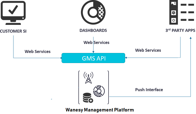
Unfortunatelly in the WMC design, MQTT is only used for push events. But… You can write an application that interfaces your AS and WMC dedicated to receive your MQTT requests from your AS and transmit downlink message to your end-device though the WMC using the GMS API web service CreateDataDown:
     AS  ---downlink---> [MQTT BROKER]--------> Application ---------CreateDataDown------> WMC ----> GW -----> End-Device
 (Publisher)                                    (Subscriber)
Is the Retain flag is set by default in the WMC Push configuration?
This option is currently not supported in the current Server Software release. This improvement will be delivered in a future release.
What about WMC GMS API?
GMS API overview
The GMS has several interfaces that can be accessed through APIs.
A RESTful Web services architecture follows basic design principles:
- It exposes a tree of resources via URI
- It is stateless. Each request from any client contains all the information necessary to service the request, and session state is held in the client.
- A resource is represented by an hypermedia type, for example JSON
- It uses HTTP methods explicitly (GET, POST, PUT, DELETE, …) and other HTTP standards
- hypertext links to reference state
- hypertext links to reference-related resources
The API version level is requested by the client using the accept HTTP header, for example here with API v1:
Accept: application/vnd.kerlink.iot-v1+jsonMany changes have been done between GMS API (WMC 3.0) and OSS API (WMC 2.3.x). Refer to the documentation section to get details of all methods available for this new WMC release.
Examples
GET https://kerlink.wanesy.fr/gms/application/customers/198/fleets?page=3&PageSize=40
This web service allows to get the page number 3 of the list of fleets of the customer 198.
| VERB | PROTOCOL | DOMAIN | PATH | QUERY STRING |
|---|---|---|---|---|
| GET | http | kerlink.wanesy.fr | /gms/application/customers/198/fleets | ?page=3&PageSize=40 |
The list of possible verbs is : GET, POST, PUT, DELETE, PATCH:
- POST: creates a new resource.
- GET: gets a resource.
- PUT: updates an existing resource.
- DELETE: deletes a resource.
- PATCH: updates a subset of fields of an existing resource.
Using the command-line These examples use the command-line program curl to make HTTP requests.
Logging in
The use of the API is bound to a fresh token. Here is how you can request for a new token:
curl -s 'https://kerlink.wanesy.fr/gms/application/login' \
  -H 'Accept: application/vnd.kerlink.iot-v1+json' \
  -X POST \
  -d '{"login":"jdoe","password":"P@ssW0rd5ecRe7"}' \
  -H 'Content-Type: application/vnd.kerlink.iot-v1+json' \
  | jq .
Here jq is used to prettify the JSON output so that it is readable and indented:
{
  "expiredDate": 1500537180050,
  "tokenType": "Bearer",
  "token": "eyJhbGciOiJIUzI1NiJ9.eyJzdWIiOiJzdXBlcmFkbW ... n6i5WboHR-I"
}
Requesting the customers list example
curl -s 'https://kerlink.wanesy.fr/gms/application/customers' \
  -H 'Accept: application/vnd.kerlink.iot-v1+json' \
  -H 'Authorization: Bearer eyJhbGciOiJIUzI1NiJ9.eyJzdWIiOiJzdXBlcmFkbW ... n6i5WboHR-I' \
  | jq .
Result:
{
  "count": 2,
  "pageSize": 50,
  "page": 1,
  "totalCount": 2,
  "list": [
    {
      "id": 130,
      ...
    }
  ],
  "nbPages": 1
}
Requesting a customer ID example
$ curl -s 'https://kerlink.wanesy.fr/gms/application/authenticatedUser' \
  -H 'Authorization: Bearer eyJhbGciOiJIUzI1NiJ9.eyJzdWIiOiJzdXBlcmFkbW ... n6i5WboHR-I' \
  -H 'Content-Type: application/vnd.kerlink.iot-v1+json;charset=UTF-8' \
  -H 'Accept: application/json, text/plain, */*' \
  | jq  '.links[] | select(.rel=="customer") | .href'
The jq filter is used to show only customer ID information. In fact, it will display the href value for all links objects for which the rel key has the customer value.
Example result with customer ID number 23:
"/application/customers/23"
Sending data to an end-device
Not all fields in TxMessageDto are required when creating a new TX message. The actual parameters to send are:
- confirmed: boolean, whether the TX message should be acknowledged (confirmed data transfer)
- contentType: enum { TEXT, HEXA }, describes how the payload is encoded
- port: integer, LoRaWAN application port number
- payload: string, data payload, either encoded as an hex string or binary data in base64
- maxAttempts: integer (optional), maximum number of transmission attempts. Only required if confirmed is true.
- ttl: integer (optional), time to live. Only required if confirmed is true.
No other parameter is supported.
How to send a downlink using GMS API ?
Here is an example with SwaggerUI.
The webservice to use is createDataDown.
For the Data Down Dto, put the following parameters values:
{
  "fPort": 1,
  "confirmed": false,
  "endDevice": {
    "devEui": "0018B20000001DB4"
  },
  "payload": "TEST DATA DOWN",
  "contentType": "TEXT"
}
The corresponding curl command is: (eventually change the server url and the token value for your needs)
curl -X POST "https://wmc-poc.wanesy.com/gms/application/dataDown" -H "accept: application/json" -H "Authorization: eyJhbGciOiJIUzI1NiJ9.eyJzdWIiOiJzdXBlcmFkbWluLWRzYyIsInJvbGUiOiJTVVBFUl9BRE1JTiIsImN1c3RvbWVySWQiOjEsIml55555ImdtcyIsImV4cCI6MTYwMjU0MjkxNn0.BSvPxtp-ICGY1Mbwq-tkxBNWQjBMg2VXKk4wtTN-t2U" -H "Content-Type: application/json" -d "{\"fPort\":1,\"confirmed\":false,\"endDevice\":{\"devEui\":\"0018B20000001DB4\"},\"payload\":\"TEST DATA DOWN\",\"contentType\":\"TEXT\"}"
How performing asynchronous requests with GMS API ?
Most of time GMS API Web services are synchronous: the user sends a request and he receives the answer in a synchronous mode.
This is the case for instance for xxx.
- getApplication
- getCustomers
- getFleets
- updateGatewayControl
- etc
But some web services are asynchronous: the user sends a request and the response is received later. The user can do anything else during this time period of processing request.
This is the case of the following web services:
- createGatewayCommand
- getGatewayControl
- etc
Two use cases need to use a different way because: - The task may take a long time to be processed (for example a spectrum with a long duration). - The task needs to be launched within another process (new thread).
Here are the steps to follow to manage correctly asynchronous web services:
- Call your web service: for instance createGatewayCommand (define the required parameters)
- Get the TaskID in the response body
- Call the web service GetTask and pass the TaskID as parameter
- Check the response body status:
- If status is OK then parse the body for the request answer.
- if status is PENDING then wait a short time and call the getTask again. Return point 3.
- if status is KO then stop. The gateway is certainly disconnected.
What to do if my ABP end-device doesn’t communicate anymore on WMC with a Data Mic Error?
| Type | Description | Potential root cause |
|---|---|---|
| DATAUP MIC ERR | Integrity message error, DataUp received with incorrect MIC, Device’s message integrity is not ensured, DataUp not decoded | Corruption of message, Device trying to mock another one (attack), either by reusing a FCNtUp either with an invalid devNonce |
What to check if I miss some messages (discontinuons frame counters)?
First, Check the radio configuration of your gateway and of your end-devices. The configuration must be exactly the same (same channels). If some channels are missing on the gateway, you can lose data.
Check the radio QoS of your gateways:
- On the WMC dahsboard, select a GW and select « Data » > « DataUp » menu options.
- Check the RSSI and SNR values of your LoRa data streams.
Check the backhaul QoS of your gateways:
- Check for network latencies by selecting the KPI « ping » of your gateway.
- Due to a bad quality of the backhaul (cellular most of the cases), the data is not forwarded to the LNS. More over UDP protocol does not certify that all messages are received by the receiver.
How to check my end-devices are well covered by my gateways?
SNR means Signal Noise Ratio
SNR ~10 dB is excellent.
SNR ~-20 dB is not good.
A positive value is good, indicates that the received signal operates above the noise floor. In this case, RSSI measures the signal level (noise level can be ignored).
A negative value indicates that the received signal operates below the noise floor. In this case the RSSI measures the noise level (signal level can be ignored).
Note that even if the signal is under the noise floor, the Semtech chip SX1301 can do its job i.e can demodulate the signal even in a noisy environment.
Note that the spreading factor can limit the receiver conditions. For each spreading factor, there is a SNR limit, if this limit is reached the receiver won’t be able to demodulate the signal.
| Spreading Factor | SNR limit (dB) |
|---|---|
| 7 | -7.5 |
| 8 | -10 |
| 9 | -12.5 |
| 10 | -15 |
| 11 | -17.5 |
| 12 | -20 |
If the SF increases by 1, the SNR limit changes by -2.5 dB.
So for a SF of 12, the SNR must be greater than -20 dB to have a good signal demodulation for the receiver.
For a SF of 7, the SNR must be greater than -7.5 dB to enable the receiver to demodulate the signal.
The RSSI (Relative Strenght Signal Indicator) is measured in dBm and is a negative value.
The closer to 0 the better the signal is.
RSSI ~-120 dBm is a weak signal (near the noise floor).
This is the minimum signal strength for LoRa reliable communications.
RSSI between - 110 dBm and -80 dBm indicates a correct signal.
RSSI ~-70 dBm is a reasonably good signal.\
RSSI ~-50 dBm is a pretty good signal.
RSSI ~ -30 dBM is an amazing signal !
RSSI > -20 dBM is too excellent ! Not possible in the field, indicates that the GW and the ED are in a Lab and are too near! LoRa is dedicated for long range applications ! :)
When the distance between the end device and the gateway increases, the signal gets weaker and therefore an increase spreading factor is needed for a lower receiver sensitivity to be able to demodulate the received signal. SF7 is used when the end-device is close to the gateway and SF12 is used when the end-device is far away from the gateway.
LoRa can transmit theoretically over 15 kms in best conditions (no physical obstacles, good antenna performance, good Tx power mode and a good node-gateway positioning).
Care about the radio signal may be affected by your environment (landscape with no obstacles, buildings, walls, vehicles, etc) and proximity of other radio devices (LTE base stations, antennas…).
Interesting documentation:
What to check if my end-device does not change spreading factor?
Check first that the ADR feature is enabled :
- Select « Management » > « End-devices »
- Select your end-device EUI
- Check that the « ADR » field is « Enabled »
- If disabled, select the pencil on the bottom of the screen and check the ADR « Enabled » box.
Check your radio QoS parameters: RSSI and SNR.
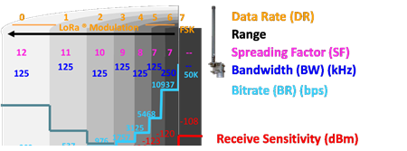
When radio QoS is not good enough, SF won’t change (using low datarate DR0 250 bits/s and SF12).
Best conditions is to have a positive SNR (nearest +10 dB) and a good signal [-110 dBm, -40 dBm].
When changing the SIM Card or changing parameters in the provisioning file of my Wirnet gateway, is a ofono service reset is mandatory?
Rebooting the gateway is sufficient to update the ofono component when changing the SIM card.
But when updating the provisioning file, ofono reset is mandatory to update the ofono component.
Avoiding to reset the Ofono service can lead to many modem errors such as “No SIM in modem” or “No APN configured” or “Not attached to the GSM network”.
If you hesitate and don't not know what to do, perform an ofono reset and a reboot!
How the Push configuration check button works ?
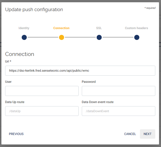
To make the check button works, it is necessary to define 2 routes on the Application server (AS):
- 1 route for uplink messages
- 1 route for downlink messages
If one of these routes is missing, the check button will return an error.
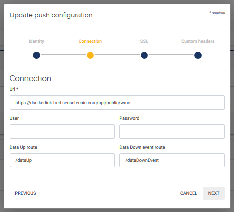
The 2 routes that must exist are the routes defined in the WMC push configuration.
For instance:
When the fields are left empty, that means that this is the default routes that will be used:
- /dataUp for the uplink route,
- /dataDownEvent for the downlink route.
Those 2 routes should exist on your application server from the ROOT_DIRECTORY path.
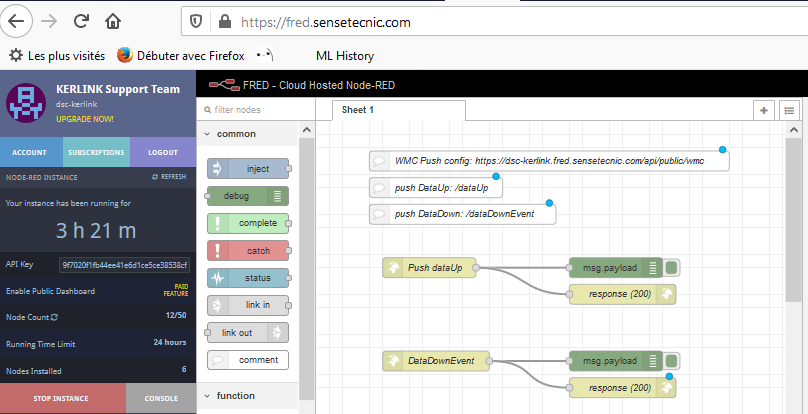
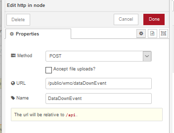
Example with NODERED:
Here is the push configuration defined WMC side:
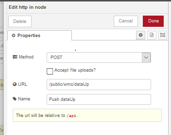
Here are the 2 objects (routes) to define in NODERED:
and their definition:
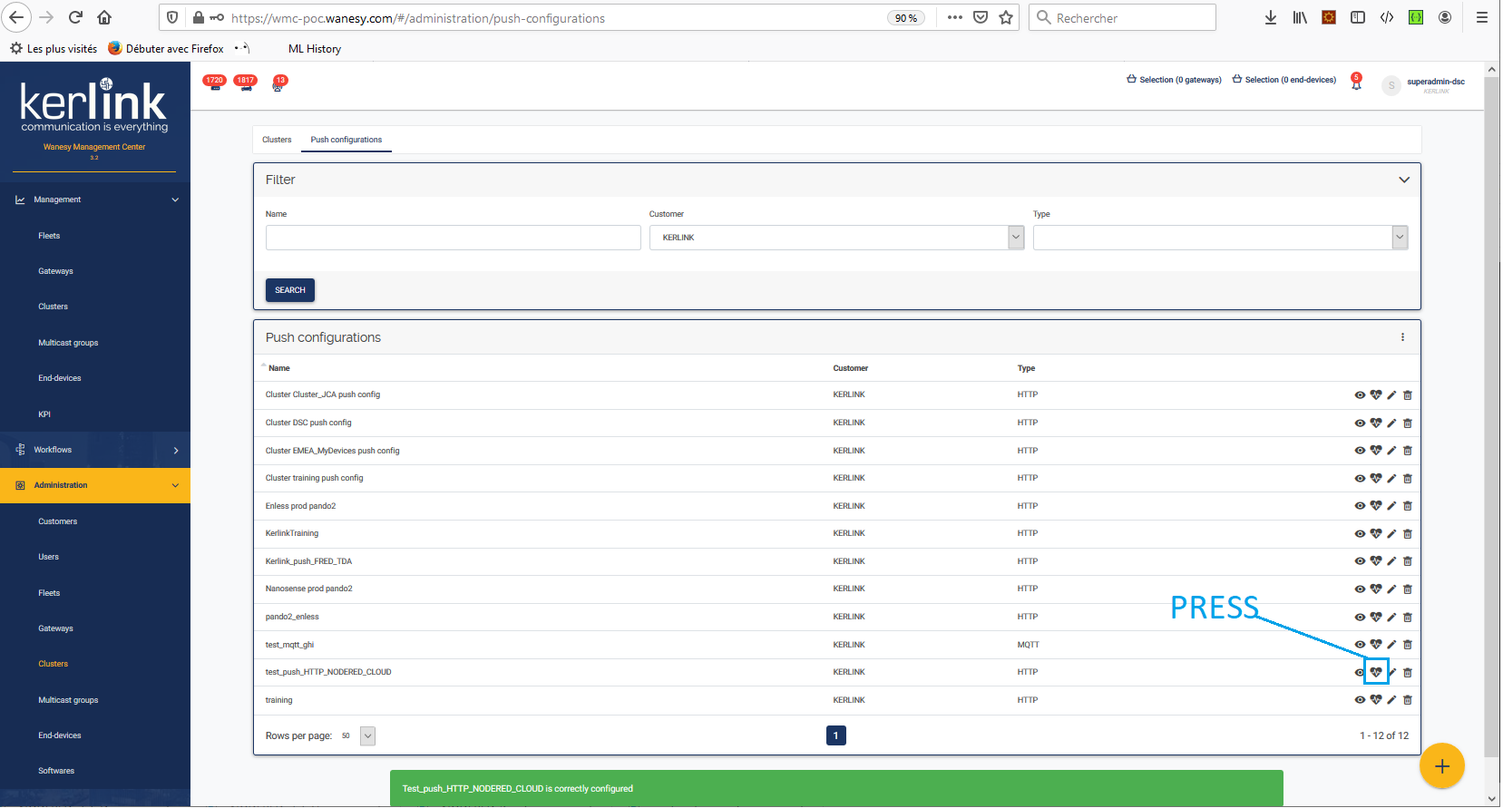
And here's the final result of pressing the push configuration check button:
The following message should be displayed at the bottom of the screen:
How to make confirmed downlink messages work ?
Confirmed downlink messages are downlink messages that are acknowledged by an end-device.
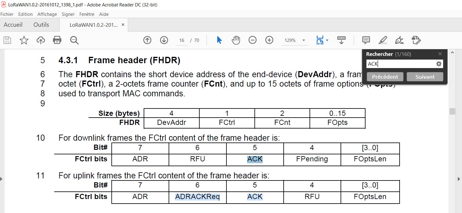
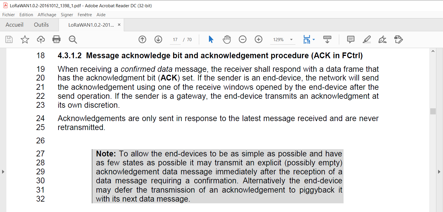
To acknowledge a confirmed downlink message, the end-device should set a specific bit (ACK) in the FCtrl field of an Unconfirmed Uplink message header as the LoRaWAN specification shows:
Here is an example of an acknowledge message received by the Packet Forwarder:
2021-06-29T13:21:24.192091+00:00 klk-lpbs-060434 lorafwd[1178]: <6> Received uplink message:
2021-06-29T13:21:24.192234+00:00 klk-lpbs-060434 lorafwd[1178]: <6> | lora uplink (45E0470C), payload 31 B, channel 868.3 MHz, crc ok, bw 125 kHz, sf 10, cr 4
2021-06-29T13:21:24.192312+00:00 klk-lpbs-060434 lorafwd[1178]: <6> | Unconfirmed Data Up, DevAddr 24000258, FCtrl [ADR] [ACK], FCnt 48, FPort 1
2021-06-29T13:21:24.192371+00:00 klk-lpbs-060434 lorafwd[1178]: <6> | - radio (00000016)
2021-06-29T13:21:24.192469+00:00 klk-lpbs-060434 lorafwd[1178]: <6> | - demodulator counter 421267796, UTC time 2021-06-29T13:21:24.110863Z, rssi -52 dB, sn
2021-06-29T13:21:24.192544+00:00 klk-lpbs-060434 lorafwd[1178]: <6> | - localization unknown, rssi -50 dB, frequency offset -2779 Hz, status (00000047)
2021-06-29T13:21:24.201154+00:00 klk-lpbs-060434 lorad[1113]: <6> Sent 1 uplink message
2021-06-29T13:21:24.202002+00:00 klk-lpbs-060434 lorafwd[1178]: <6> Uplink message (6C0C) sent
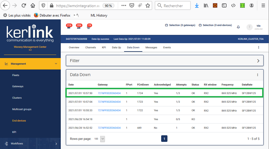
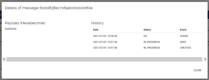
Caution: when creating the confirmed downlink message, it is very important to set properly the timeout value if you don't want to see a KO as the final status of the sending message.
To create a confirmed downlink message, you have to enable the option “Acknowlegement”.
For class A end-devices, the timeout value must be greater than the time period of uplink messages. For instance, if your uplink messages periodicity is 60s, you must set a timeout value at least equal to 60s.
In this example, the periodicity of uplinks is 8s, so the timeout value has been set to 8s.
How to make the Multicast Class C works ?
The Multicast Class C has the objective to send a single message as a brodcasting manner to a group of end-devices.
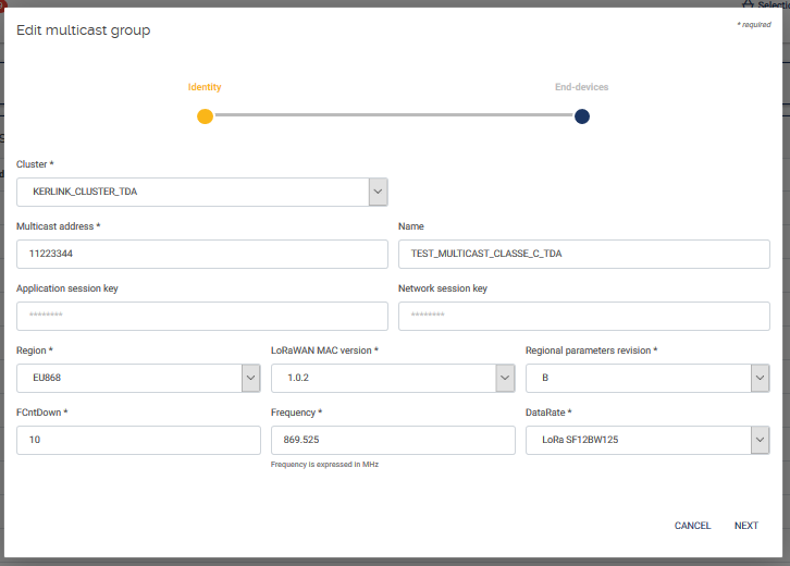
To achieve this, you must define a Multicast group with the following definition:
- A cluster name: the same cluster that the end-devices belong to.
- A multicast address: DevAddr, a 32 bit network address (must be unique and not belong to an existing end-device)
- An application session key (AppSKey) and a network session key (NWkSKey) used for frames encryption, 32 digits hexadecimal string.
- A fixed frequency in MHz (float32) and a DataRate (a string formatted as “SFxxBWyyy” with xx from 7 to 12 and yyy = 125/250/500 for LoRa modulation or yyy=5000 for FSK modulation)
- A frame counter (optional): FCntDown
- The LoRaWAN MAC version: for Europe 868 MHz, select 1.0.2 MAC version and Regional parameters B revision to be compatible with WMC 2.x
The multicast address and associated network session key and application session key must come from the application layer. Class-C multicast downlinks SHALL NOT carry MAC commands.
For instance:
Note that all the end-devices must be flashed with 2 pairs of keys:
- The end-device's own keys (OTAA or ABP keys).
- the Multicast group keys defined above.
So each end-device has 2 devAddr:
- its own devAddr.
- the Multicast group devAddr.
We recommend to use a channel frequency which duty cycle is the most permissive: for instance using 869.525Mhz allows a duty cycle of 10% instead of using 868.1Mhz that allows a duty cycle of only 1%.
In the same order, we recommend to use a SF7BW125 instead of SF12BW125 to use the highest datarate as possible and to minimize the duty cycle.
The Multicast class C uses Unconfirmed downlink messages and not Confirmed downlink messages.
That's why you have no timeout and no retry count to specify.
So there is no information about the fact that the downlink message has been correctly received by the end-devices.
Care to not use FPort 0 reserved for MAC commands.
Example:
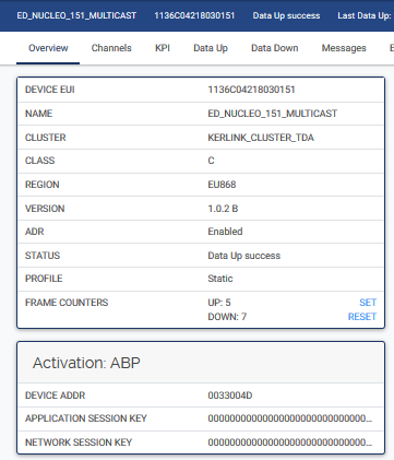
Using Semtech Nucleo class C end-devices:
Device Nucleo Semtech 151

    devEUI : 1136C04218030151
    devAddr : 0033004D
    AppSKey : 00000000000000000000000000000000
    NwkSKey : 00000000000000000000000000000000
    Class C
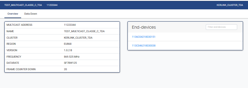
Adding end-devices in the Multicast group:
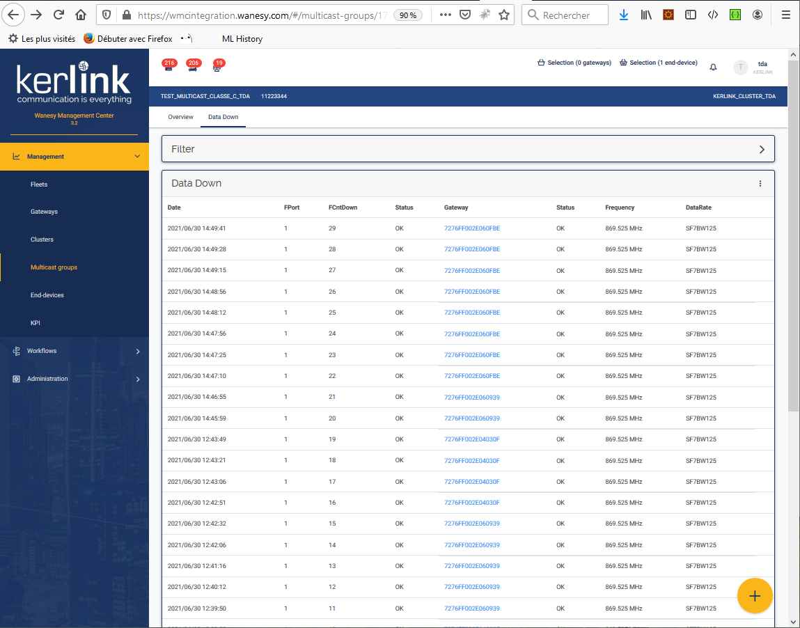
Sending data down messages:
How to switch the cellular backhaul from 4G to 3G ?
Connect to the gateway (for instance over the remote shell) and type the following command:
For stations using a quectel modem (Wirnet iStation, Wirnet iFemtoCell Evolution):
dbus-send --system --type=method_call --print-reply --dest=org.ofono /quectelqmi_0 org.ofono.RadioSettings.SetProperty string:"TechnologyPreference" variant:string:"umts"
For stations using a sierra modem (Wirnet iBTS):
dbus-send --system --type=method_call --print-reply --dest=org.ofono /sierra_0 org.ofono.RadioSettings.SetProperty string:"TechnologyPreference" variant:string:"umts"
Note that this configuration is persistent (is not removed when rebooting the gateway).
How to switch the cellular backhaul from 3G to 4G ?
Connect to the gateway (for instance over the remote shell) and type the following command:
For stations using a quectel modem (Wirnet iStation, Wirnet iFemtoCell Evolution):
dbus-send --system --type=method_call --print-reply --dest=org.ofono /quectelqmi_0 org.ofono.RadioSettings.SetProperty string:"TechnologyPreference" variant:string:"lte"
For stations using a sierra modem (Wirnet iBTS):
dbus-send --system --type=method_call --print-reply --dest=org.ofono /sierra_0 org.ofono.RadioSettings.SetProperty string:"TechnologyPreference" variant:string:"lte"
Note that this configuration is persistent (is not removed when rebooting the gateway).
How to acknowledge an alarm using GMS API
Acknowledging an alarm using GMS API can be useful to remove the alarm from the active alarms list. The main advantage of doing this over GMS API is the fact that this task can be done using a script (bash, python, javascript, java, etc…) at the application level on any remote machine. No human action is required (selecting the bell icon to cancel the alarm).
Here is the procedure:
- Call the Login web service to get your session token
- Copy the token value in the Authorize field
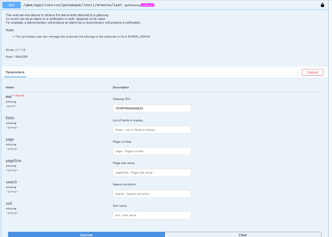
- Call the web-service getGatewayLastEvents to get the list of the last events of a given gateway
- Get the eventID in the response
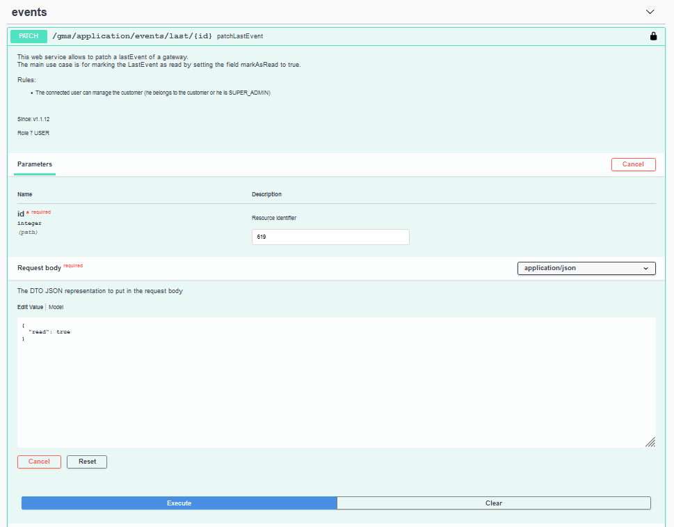
- Put this eventID in the patchLastEvent request
For instance :
I want to acknowledge the “POWER_LOST” alarm for the gateway 707600FF54040023
I'm skipping the login procedure that is explained in the WMC WIKI here: GMS API Login
I'm calling the web service getGatewayLastEvents passing the gateway EUI as parameter:
It is possible to filter events using the search field (filtering on the event category, for instance).
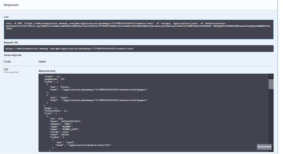
The response is :
From the response, I can get the eventID (here 619) that will be used in the following request.
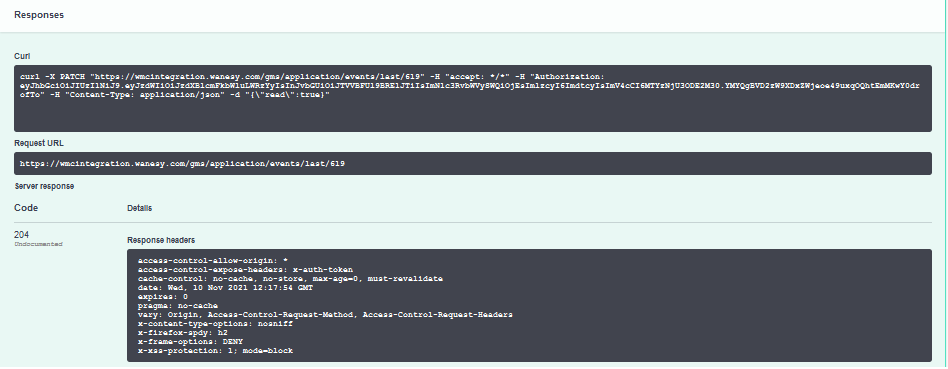
Calling the patchLastEvent webservice with the “eventID” parameters and “read” parameter with the value “true”:
If the response is 20x then the request has been correctly executed.
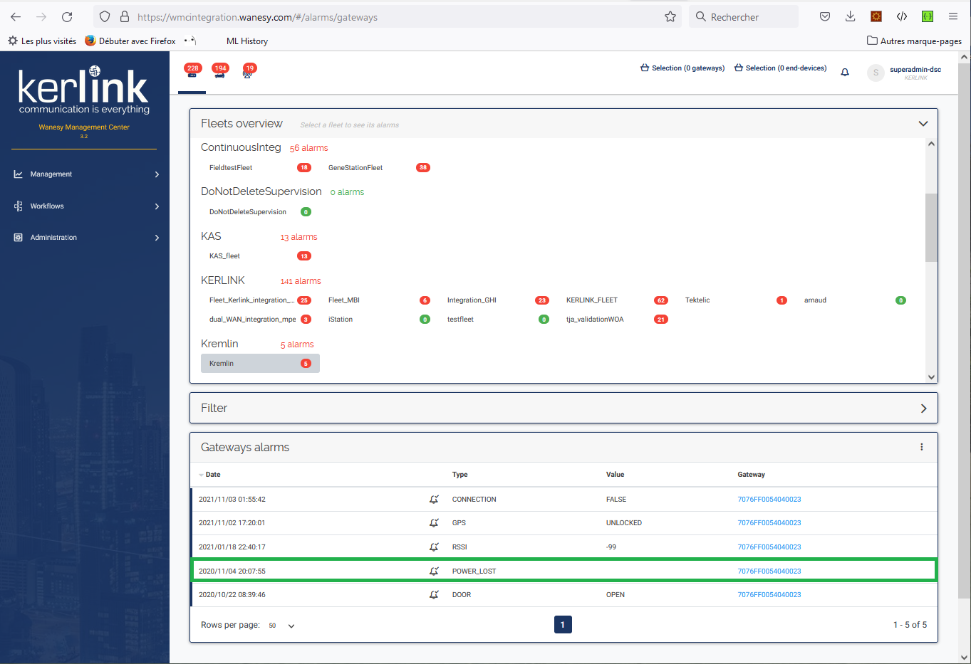
The event has been removed from the active alarms list :
Note: I have also acknowledged the “GPS_UNLOCKED” alarm in the same manner.
How to get unsent push messages using GMS API
For some unknown reasons, the push can fail for instance when an outage occurs on the customer's Application server.
To avoid losing application messages, the following procedure can be applied to retrieve unsent messages over GMS API.
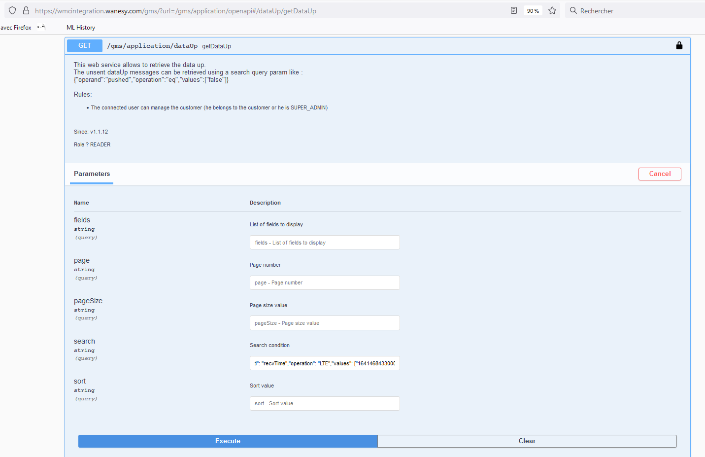
The webservice to use is getDataUp with a specific search criteria to get unsent message :
{"operand":"pushed","operation":"eq","values":["false"]}
This search criteria will return all the unsent messages since the WMC was turned online. Maybe you will desire to filter on a given time period. To achieve this, the following search criteria can be used :
{"operator": "AND","conditions": [{"operand": "pushed","operation": "EQ","values": ["false"]},{"operand": "recvTime","operation": "GTE","values": ["<TIME START in ms>"]},{"operand": "recvTime","operation": "LTE","values": ["<TIME END in ms>" ]} ]}
A more readable search criteria :
  {
			  "operator": "AND",
			  "conditions": [
			    {
			      "operand": "pushed",
			      "operation": "EQ",
			      "values": [
			        "false"
			      ]
			    },
			    {
			      "operand": "recvTime",
			      "operation": "GTE",
			      "values": [
			        "<TIME START in ms>"
			      ]
			    },
							    {
			      "operand": "recvTime",
			      "operation": "LTE",
			      "values": [
			        "<TIME END in ms>"
			      ]
			    }
			  ]
}
For instance:
Filtering messages from: 2022-01-05 13:28:18 UTC+2 to: 2022-01-06 13:27:13 UTC+2
Note: use EPOCH Converter tool to convert these dates to Epoch timestamps in ms and don't forget to use GMT/UTC values !
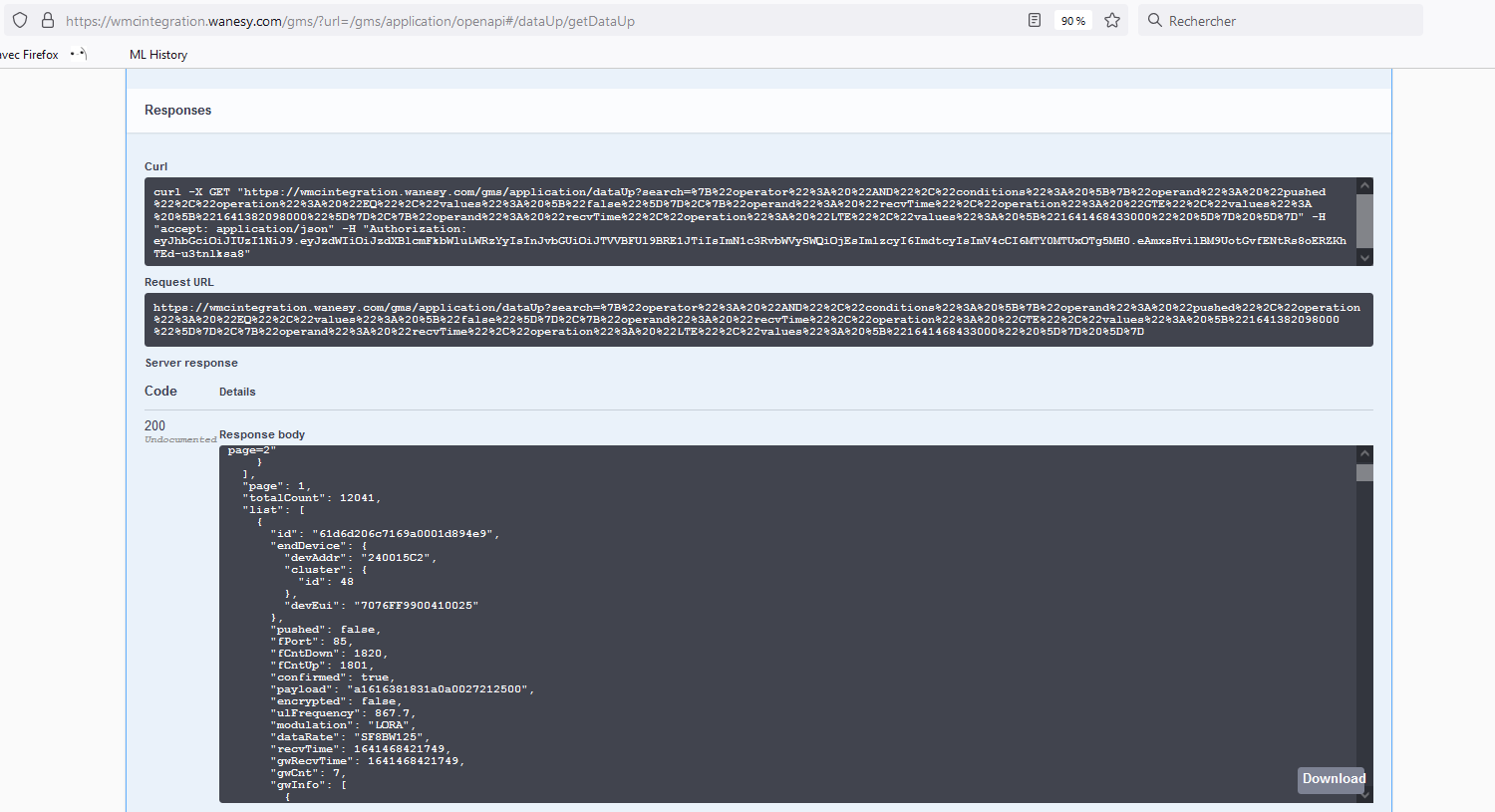
{"operator": "AND","conditions": [{"operand": "pushed","operation": "EQ","values": ["false"]},{"operand": "recvTime","operation": "GTE","values": ["1641382098000"]},{"operand": "recvTime","operation": "LTE","values": ["1641468433000" ]} ]}
Testing:
How to configure DIVERSITY on iBTS?
Please see in iSeries Wiki FAQ: How to configure DIVERSITY on iBTS?
How to check OpenVPN certificates validity?
You can use following commands, depending on the KerOS version installed on the gateways.
On version 3x:
openssl pkcs12 -info -in /etc/openvpn/client-openvpn.p12 -nokeys -password pass: | openssl x509 -noout -enddate
On version 4x:
grep 'Not After' /.update/update.log | awk 'END {print}'
On version 5x:
openssl pkcs12 -info -in /etc/openvpn/bscc.p12 -nokeys -password file:/etc/openvpn/bscc.password| openssl x509 -noout -enddate
Which network configuration should be done to connect my gateway to Wanesy™ Management Cockpit?
Administrative information
You can find in following document, the administrative information you should know as a user of Kerlink’s products: Administrative information

